Hey Zusammnen,
Setup: Lolin d32 und Basis Mini 4L Platine rev3.
SD Karte 16GB und 32GB Fat32 formatiert
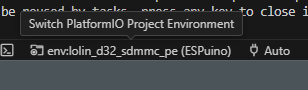
SoftwareProfil: env:lolin_d32_sdmmc_pe (nicht verändert)
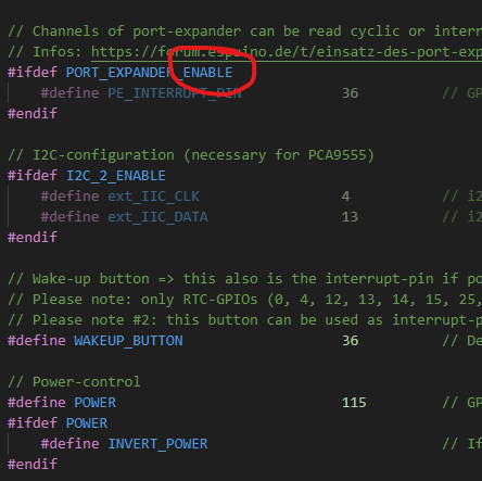
Power: 115
Expander enabled
Power Inverted
Leider wird die SD Karte nicht gemounted. Habe bisher keine Hardware angeschlossen.
Config:
// clang-format off
#ifndef __ESPUINO_SETTINGS_LOLIN_D32_H__
#define __ESPUINO_SETTINGS_LOLIN_D32_H__
#include "Arduino.h"
//######################### INFOS ####################################
/* This is a PCB-specific config-file for *Wemos Lolin32 D32 with port-expander PCA9555PW and SD_MMC*.
PCB: t.b.a.
Forum: https://forum.espuino.de/t/espuino-minid32-pro-lolin-d32-pro-mit-sd-mmc-und-port-expander-smd/866
Infos: https://www.wemos.cc/en/latest/d32/d32.html
Schematics Lolin D32: https://www.wemos.cc/en/latest/_static/files/sch_d32_v1.0.0.pdf
Schematics PCB: t.b.a.
Caveats: GPIO35 (battery monitoring). GPIOs 16+17 are not used by the PCB.
Status:
tested with PN5180 + SD_MMC (by biologist79)
*/
//################## GPIO-configuration ##############################
// Please note: GPIOs 34, 35, 36, 39 are input-only and don't have internal pullup-resistors.
// So if connecting a button to these, make sure to add a 10k-pullup-resistor for each button.
// Further infos: https://randomnerdtutorials.com/esp32-pinout-reference-gpios/
// All GPIOs >=100 and <= 115 are connected to a port-expander
#ifdef SD_MMC_1BIT_MODE
// (MOSI) 15 CMD
// (SCK) 14 SCK
// (MISO) 2 D0
#else
// SPI-SD IS NOT SUPPORTED BY THIS PCB - DON'T USE INTERNAL SD-READER!
#define SPISD_CS 99 // GPIO for chip select (SD)
#ifndef SINGLE_SPI_ENABLE
#define SPISD_MOSI 99 // GPIO for master out slave in (SD) => not necessary for single-SPI
#define SPISD_MISO 99 // GPIO for master in slave ou (SD) => not necessary for single-SPI
#define SPISD_SCK 99 // GPIO for clock-signal (SD) => not necessary for single-SPI
#endif
#endif
// RFID (via SPI)
#define RST_PIN 99 // Used as dummy for RC522
#define RFID_CS 21 // GPIO for chip select (RFID)
#define RFID_MOSI 23 // GPIO for master out slave in (RFID)
#define RFID_MISO 19 // GPIO for master in slave out (RFID)
#define RFID_SCK 18 // GPIO for clock-signal (RFID)
#ifdef RFID_READER_TYPE_PN5180
#define RFID_BUSY 33 // PN5180 BUSY PIN
#define RFID_RST 22 // PN5180 RESET PIN
#define RFID_IRQ 99 // Depending on your configuration this needs to be adjusted to 32.
#endif
// I2S (DAC)
#define I2S_DOUT 25 // Digital out (I2S)
#define I2S_BCLK 27 // BCLK (I2S)
#define I2S_LRC 26 // LRC (I2S)
// Rotary encoder
#ifdef USEROTARY_ENABLE
//#define REVERSE_ROTARY // To reverse encoder's direction; switching CLK / DT in hardware does the same
#define ROTARYENCODER_CLK 34 // rotary encoder's CLK
#define ROTARYENCODER_DT 39 // 39 = 'VN'; rotary encoder's DT
#endif
// Amp enable (optional)
#define GPIO_PA_EN 108 // To enable/disable amp for loudspeaker; connected to port-expander
// Control-buttons
#define NEXT_BUTTON 102 // Next-Button: connected to port-expander
#define PREVIOUS_BUTTON 100 // Prev-Button: connected to port-expander
#define PAUSEPLAY_BUTTON 101 // Pplay-Button: connected to port-expander
#define ROTARYENCODER_BUTTON 103 // Set to 99 to disable the button; connected to port-expander
#define BUTTON_4 104 // Button 4: connected to port-expander
#define BUTTON_5 105 // Button 5: connected to port-expander
//#define BUTTONS_LED 114 // Powers the LEDs of the buttons. Make sure the current consumed by the LEDs can be handled by the used GPIO
// Channels of port-expander can be read cyclic or interrupt-driven. It's strongly recommended to use the interrupt-way!
// Infos: https://forum.espuino.de/t/einsatz-des-port-expanders-pca9555/306
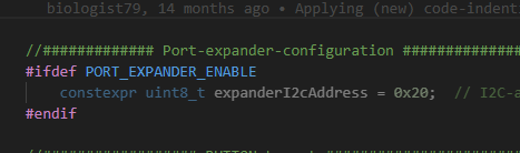
#ifdef PORT_EXPANDER_ENABLE
#define PE_INTERRUPT_PIN 36 // GPIO that is used to receive interrupts from port-expander + to wake up ESP32
#endif
// I2C-configuration (necessary for PCA9555)
#ifdef I2C_2_ENABLE
#define ext_IIC_CLK 4 // i2c-SCL (clock)
#define ext_IIC_DATA 13 // i2c-SDA (data)
#endif
// Wake-up button => this also is the interrupt-pin if port-expander is enabled!
// Please note: only RTC-GPIOs (0, 4, 12, 13, 14, 15, 25, 26, 27, 32, 33, 34, 35, 36, 39, 99) can be used! Set to 99 to DISABLE.
// Please note #2: this button can be used as interrupt-pin for port-expander. If so, all pins connected to port-expander can wake up ESPuino.
#define WAKEUP_BUTTON 36 // Defines the button that is used to wake up ESPuino from deepsleep; set to 99 to disable
// Power-control
#define POWER 115 // GPIO used to drive transistor-circuit, that switches off peripheral devices while ESP32-deepsleep
#ifdef POWER
#define INVERT_POWER // If enabled, use inverted logic for POWER circuit, that means peripherals are turned off by writing HIGH
#endif
// (optional) Neopixel
#define LED_PIN 12 // GPIO for Neopixel-signaling
// (optinal) Headphone-detection
#ifdef HEADPHONE_ADJUST_ENABLE
//#define DETECT_HP_ON_HIGH // Per default headphones are supposed to be connected if HT_DETECT is LOW. DETECT_HP_ON_HIGH will change this behaviour to HIGH.
#define HP_DETECT 107 // GPIO that detects, if there's a plug in the headphone jack or not; connected to port-expander
#endif
// (optional) Monitoring of battery-voltage via ADC
#ifdef MEASURE_BATTERY_VOLTAGE
#define VOLTAGE_READ_PIN 35 // GPIO used to monitor battery-voltage. Don't change, it's built in
constexpr float referenceVoltage = 3.30; // Voltage between 3.3V and GND-pin at the develboard in battery-mode (disconnect USB!)
constexpr float offsetVoltage = 0.1; // If voltage measured by ESP isn't 100% accurate, you can add an correction-value here
#endif
// (optional) For measuring battery-voltage a voltage-divider is already onboard. Connect a LiPo and use it!
#ifdef MEASURE_BATTERY_VOLTAGE
constexpr uint16_t rdiv1 = 100; // Don't change, it's built in
constexpr uint16_t rdiv2 = 100; // Don't change, it's built in
#endif
// (optional) hallsensor. Make sure the GPIO defined doesn't overlap with existing configuration. Please note: only user-support is provided for this feature.
#ifdef HALLEFFECT_SENSOR_ENABLE
#define HallEffectSensor_PIN 32 // GPIO that is used for hallsensor (ADC); user-support: https://forum.espuino.de/t/magnetische-hockey-tags/1449/35
#endif
// (Optional) remote control via infrared
#ifdef IR_CONTROL_ENABLE
#define IRLED_PIN 5 // GPIO where IR-receiver is connected (only tested with VS1838B)
#define IR_DEBOUNCE 200 // Interval in ms to wait at least for next signal (not used for actions volume up/down)
// Actions available. Use your own remote control and have a look at the console for "Command=0x??". E.g. "Protocol=NEC Address=0x17F Command=0x68 Repeat gap=39750us"
// Make sure to define a hex-code not more than once as this will lead to a compile-error
// https://forum.espuino.de/t/neues-feature-fernsteuerung-per-infrarot-fernbedienung/265
#define RC_PLAY 0x68 // command for play
#define RC_PAUSE 0x67 // command for pause
#define RC_NEXT 0x6b // command for next track of playlist
#define RC_PREVIOUS 0x6a // command for previous track of playlist
#define RC_FIRST 0x6c // command for first track of playlist
#define RC_LAST 0x6d // command for last track of playlist
#define RC_VOL_UP 0x1a // Command for volume up (one step)
#define RC_VOL_DOWN 0x1b // Command for volume down (one step)
#define RC_MUTE 0x1c // Command to mute ESPuino
#define RC_SHUTDOWN 0x2a // Command for deepsleep
#define RC_BLUETOOTH 0x72 // Command to enable/disable bluetooth
#define RC_FTP 0x65 // Command to enable FTP-server
#endif
#endif
hat Jemand eine Idee für mich?