Hey folks. I’m a hardware developer, the one behind Sonocotta audio development boards. I’ve created quite a few of them over the last few years, and in most cases I was using 3-rd party software, like ESPHome and squeezelite-esp32. One person pointed me out to this comunity and I thought, this looks brilliant and I can make a hardware that would be a great fit.
In fact I’ve created a very similar board few years back, called loud-esp, that checks few boxes already
ESP32 with PSRAM
Dual MAX98357 DAC
LiPo management and low power operation
SD-CARD over SPI
Rotary encoder header
SPI LCD header, that can easily be used for the RFID module
IR reader (not sure if it is very helpful though)
WS2812 LED
I think the only part that is missing are few extra buttons, and maybe few more ws2812 LEDs.
So it cross my mind to create a special ESPuino edition of this board, specifically tailored for ESPuino use case. Currently I’m considering switching over to ESP32-S3, since it is much more capable chip and I’m not using Bluetooth that much (it is rubbish on the ESP32, if you ask me).
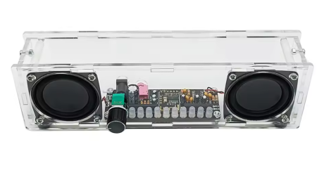
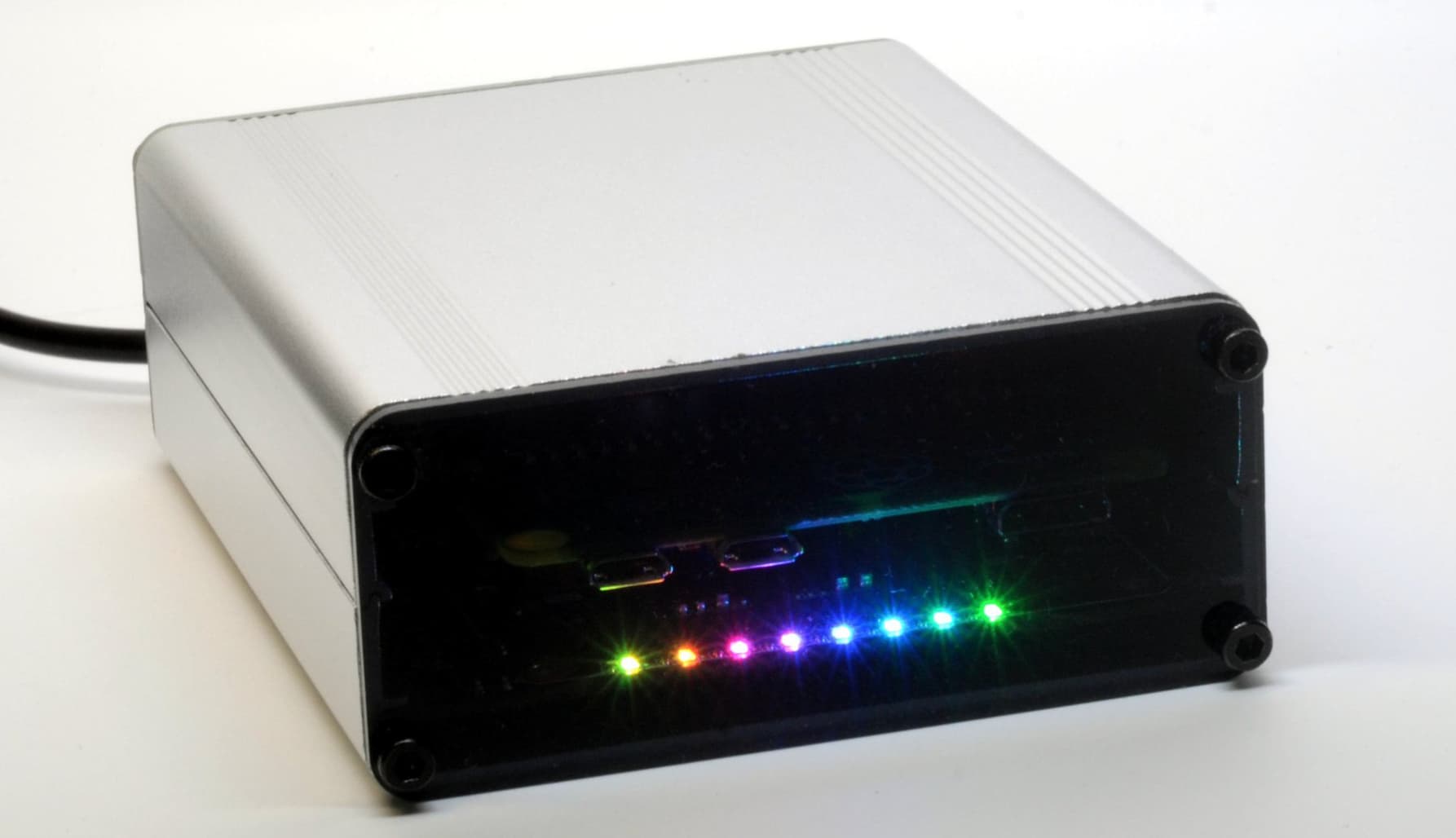
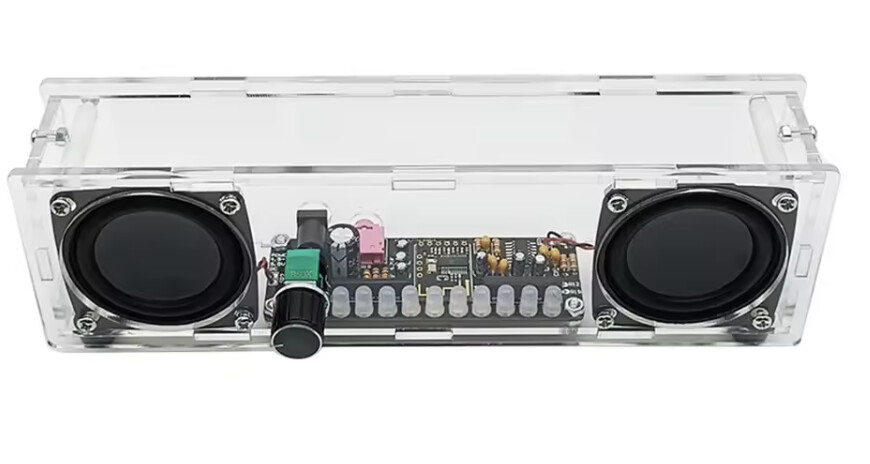
And second concern, I woudl like this board to be a fit for existing case, Ideally laser cut, not 3d-printed, so it can be produced in volumes without major issues. I’ve obtained this case and couple of speakers to experiment, but ultimately, I’d need to design a variation of it, to fit all the peripherals.
Just wanted to hear potential customer „wish list“, before I set to draw a PCB for it.
Fine, but most people (I guess) would use only one of them. Should be possible to use only one of them while this one plays both channels.
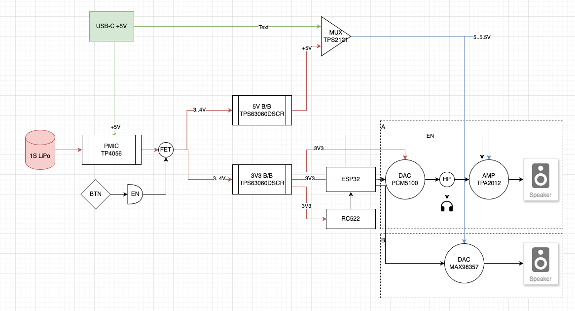
Some users still ask for LiPo, but LiFePO4 is safer. Unfortunately, when it somes to ready-to-use battey packs, we only got one source: EREMIT 3.2V 6Ah LiFePo4 Akku Pack.
„Unfortunately“ because this pack has plug-wise twisted polarity. This makes it somehow impossible to provide a board, that can be used for LiPo + LiFePO4, while this would absolutely be possible with a boost-buck-converter.
SDMMC is the way to to. Needs lees GPIOs and is much faster.
Absolutely necessary.
As of now we don’t use a display. However, keep in mind that especially PN5180 needs a lot of more GPIOs. By the way: PN5180 seems to work better with 5 V on one pin. However, this would make it necessary to have 3,3 + 5 V. Don’t know if it’s worth it.
I’ll stick with good old ESP32, since SDIO issue seems to have a reliable fix.
Dual MAX98357, you can configure them to work in mono mode with a jumper
I’ll stay with 18650 LiPo, they are far easier to find and available with built-in protection. I have worked with them for years, and so far, no incidents. I used TP4056 Ic among others and quite happy with it.
SDMMC it is
The rotary encoder is okay. Does software need interrupt-enabled pins, or will any inputs do?
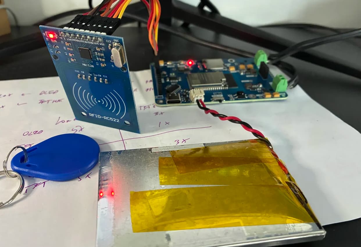
I think I’ll stick with RC522 for simplicity, at least for now
IR reader and a few WS2812 can stay
I don’t have buttons now, but since GPIO expander is necessary, it should not be an issue. I’m thinking of using touch sensor buttons, so I don’t have to cut the case open (should be good for audio)
FLASH and RESET buttons are there already
The rest can be empty headers on the PCB, doesn’t cost me extra
Any feedback regarding the case? Any good examples made by community people?
Yes, I’m using auto-flash circuitry. Just used to have both of them just in case:)
Headphones connector: with MAX98357 it is only possible to do mono, since they use push-pull output drivers. Having another DAC for headphones would be overkill i think
Bar on the bottom or top part will do it i think. Buttons can be a banch of touch sensors on the top
I can put external pullups, but I can’t add interrups support
I know it is possible. Just saying $5+ extra cost just for HP output seems to be an overkill. Alternatively, I would use PCM5100 with a D-class amp like in Amped-ESP32. But again, multiplies the cost. I’m aiming for a solution that can be produced in quantities at a reasonable price.
Yes, this is already a part of loud-esp board. Thanks for noting
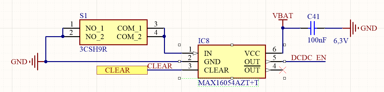
I’m planning to use latch button that would cut the power altogether. I used that before, and it gives a lot of confidence that board would not draw any unnecessary power while idling
Instead of latch button I prefer momentary button and latch controller IC. It is more elegant solution because all buttons can be the same and standby current is also neglegible.
Hey @Steevie85 thanks for suggestion. Do you have a specific IC in mind? I was thinking doing this in discrete (with a push button), but I’d prefer a ready-to-use IC for a reasonable price
Had a lot of Windows users, that had problems with flashing their ESPs. It turned out a capacitor’s value was too low. This being said: I’d strongly recommend to increase C7’s capacity to 1 µF.
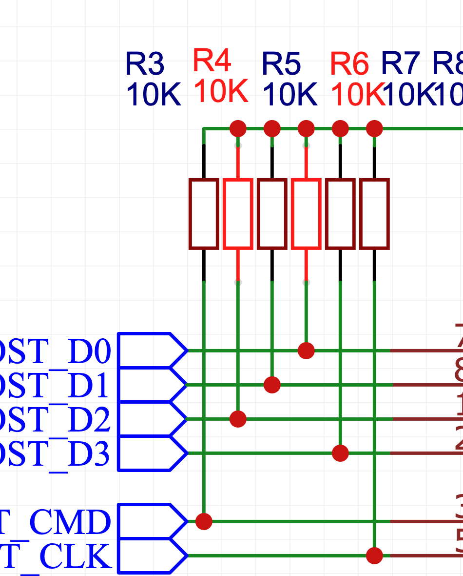
IO2 is pulled up via sd module. R5 should be omitted as otherwise ESP32 is not flashable while sd card is inserted. We already discussed it, so I guess it’s there by mistake.
Simply switching off MAX98357a can lead to ugly noises when SD_MODE isn’t pulled down first. That’s why we use PA_EN which means: 3,3 V to SD_MODE are provided by the port expander. I know it’s different in your case as you plan to switch off supply completely (no deep sleep) but maybe it makes sense to have it somehow controllable.
If I was you, I’d arrange those two MAX more flexible. Which means: first MAX plays stereo per default but can be changed via solder jumper to play left channel only. Second MAX plays right channel but needs to be enabled first by solder jumper. Can provide details if this is of interest.
I’m using naked sd-card connector, so nothing is pulled by default. I put all pullups to indicate reference schematics, but highlighted resistors will not be placed on the board
Yes, I did test specifically those LEDs, they work fine with anything between 3 and 5V on power and 3.3v logic levels. I didn’t want to power them from 3V3 line, since 12 LEDs can make the power line quite noisy, causing the ESP32 to run unstable.
Good catch, I’ll connect DAC_EN to pin 13, since 4-bit SDIO is not much better than 1-bit anyway. Probably will use another SDIO pin for charger TP4056 charge states
I want to use the below case, so I’d prefer to stick to stereo by default, and mono can be optional (I think I even can make it solder-less, you’d cut the wire to turn it to mono)