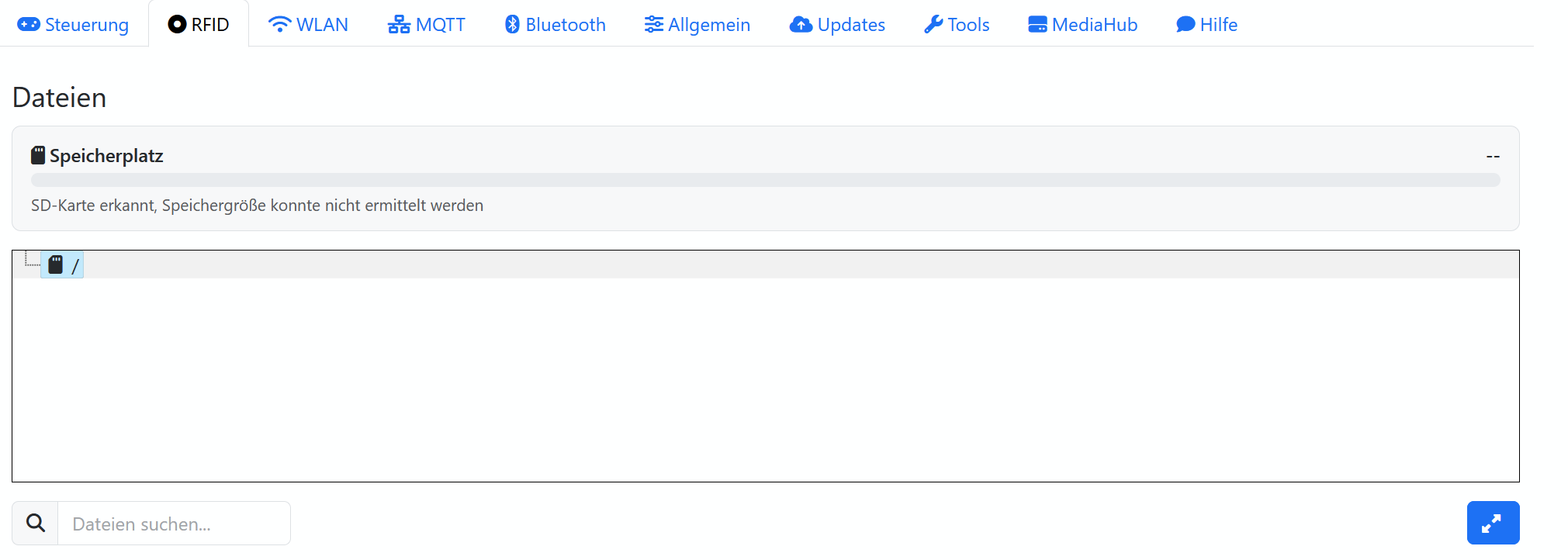
mini4l mit Wemos D32pro, RC522, 24er Neopixel, kein Drehencoder, 5x Touchsensoren, ein Taster.
Folgende Einstellungen:
settings.h
// clang-format off

#ifndef __ESPUINO_SETTINGS_H__
    	#define __ESPUINO_SETTINGS_H__
        #include "Arduino.h"
        #include "values.h"
#if __has_include("settings-override.h")
    	#include "settings-override.h"
#else
	//######################### INFOS ####################################
	// This is the general configfile for ESPuino-configuration.

	//################## HARDWARE-PLATFORM ###############################
	/* Make sure to also edit the configfile, that is specific for your platform.
	If in doubts (your board is not listed) use HAL 7

	!!!Only ESP32 with PSRAM are supported!!!

	HAL 4: Wemos Lolin D32 pro                  => settings-lolin_D32_pro.h
	HAL 5: Lilygo T8 (V1.7)                     => settings-ttgo_t8.h
	HAL 6: ESPuino complete                     => settings-complete.h
	HAL 7: Lolin D32 pro SDMMC Port-Expander    => settings-lolin_d32_pro_sdmmc_pe.h
	HAL 99: custom                              => settings-custom.h
	*/
	#ifndef HAL             // Will be set by platformio.ini. There's no need to adjust this manually right here
		#define HAL 4
	#endif

	// Enforce port expander for some HALs because it's mandatory for those and users constantly forget it. Endless story...
	#if (HAL == 6) || (HAL == 7)
		#define PORT_EXPANDER_ENABLE
	#endif

	//########################## MODULES #################################
	//#define PORT_EXPANDER_ENABLE          // When enabled, buttons can be connected via port-expander PCA9555 (https://forum.espuino.de/t/einsatz-des-port-expanders-pca9555/306)
	//#define I2S_COMM_FMT_LSB_ENABLE       // Enables FMT instead of MSB for I2S-communication-format. Used e.g. by PT2811. Don't enable for MAX98357a, AC101 or PCM5102A)
	#define MDNS_ENABLE                     // When enabled, you don't have to handle with ESPuino's IP-address. If hostname is set to "ESPuino", you can reach it via ESPuino.local
	#define MQTT_ENABLE                     // Make sure to configure mqtt-server and (optionally) username+pwd
	//#define FTP_ENABLE                      // Enables FTP-server; DON'T FORGET TO ACTIVATE AFTER BOOT BY PRESSING PAUSE + NEXT-BUTTONS (IN PARALLEL)!
	#define NEOPIXEL_ENABLE                 // Don't forget configuration of NUM_LEDS if enabled
	#define LANGUAGE DE                     // DE = deutsch; EN = english: FR = french
	#define HEADPHONE_ADJUST_ENABLE         // Used to adjust (lower) volume for optional headphone-pcb (refer maxVolumeSpeaker / maxVolumeHeadphone) and to enable stereo (headphones are always stereo, even if mono-playback is enabled via GUI)
	#define SHUTDOWN_IF_SD_BOOT_FAILS       // Will put ESP to deepsleep if boot fails due to SD. Really recommend this if there's in battery-mode no other way to restart ESP! Interval adjustable via deepsleepTimeAfterBootFails.
	#define MEASURE_BATTERY_VOLTAGE         // Enables battery-measurement via GPIO (ADC) and voltage-divider
	//#define USEROTARY_ENABLE                // If rotary-encoder is used (don't forget to review WAKEUP_BUTTON if you disable this feature!)
	#define BLUETOOTH_ENABLE                // If enabled and bluetooth-mode is active, you can stream to your ESPuino or to a headset via bluetooth (a2dp-sink & a2dp-source). Note: This feature consumes a lot of resources and the available flash/ram might not be sufficient.
	//#define IR_CONTROL_ENABLE             // Enables remote control (https://forum.espuino.de/t/neues-feature-fernsteuerung-per-infrarot-fernbedienung/265)
	//#define HALLEFFECT_SENSOR_ENABLE      // Support for hallsensor. For fine-tuning please adjust HallEffectSensor.h Please note: only user-support provided (https://forum.espuino.de/t/magnetische-hockey-tags/1449/35)

	//################## select SD card mode #############################
	//#define SD_MMC_1BIT_MODE              // run SD card in SD-MMC 1Bit mode (using GPIOs 15 + 14 + 2 is mandatory!)
	//#define SINGLE_SPI_ENABLE             // If only one SPI-instance should be used instead of two (not yet working!)
	//#define NO_SDCARD                     // enable to start without any SD card, e.g. for a webplayer only. SD card Settings above will be ignored


	//################## select RFID reader ##############################
	// Runtime RFID reader selection is now supported via web interface
	// Runtime RFID reader type configuration
	// 0 = Auto-detect
	// 1 = MFRC522 (SPI)
	// 2 = MFRC522 (I2C)
	// 3 = PN5180
	#define RFID_READER_TYPE_RUNTIME 0   // Default to Auto-detect

	#if defined(RFID_READER_TYPE_RUNTIME)
		#define MFRC522_ADDR 0x28           // default I2C-address of MFRC522
	#endif

	//############# Port-expander-configuration ######################
	#ifdef PORT_EXPANDER_ENABLE
		constexpr uint8_t expanderI2cAddress = 0x20;  // I2C-address of PCA9555 (0x20 is true if PCA's pins A0+A1+A2 are pulled to GND)
	#endif

	//################## BUTTON-Layout ##################################
	/* German documentation: https://forum.espuino.de/t/das-dynamische-button-layout/224
	Please note the following numbers as you need to know them in order to define actions for buttons.
	Even if you don't use all of them, their numbers won't change
		0: NEXT_BUTTON
		1: PREVIOUS_BUTTON
		2: PAUSEPLAY_BUTTON
		3: ROTARYENCODER_BUTTON
		4: BUTTON_4
		5: BUTTON_5

	Don't forget to enable/configure those buttons you want to use in your develboard-specific config (e.g. settings-custom.h)

	Single-buttons [can be long or short] (examples):
		BUTTON_0_SHORT => Button 0 (NEXT_BUTTON) pressed shortly
		BUTTON_3_SHORT => Button 3 (ROTARYENCODER_BUTTON) pressed shortly
		BUTTON_4_LONG => Button 4 (BUTTON_4) pressed long

	Multi-buttons [short only] (examples):
		BUTTON_MULTI_01 => Buttons 0+1 (NEXT_BUTTON + PREVIOUS_BUTTON) pressed in parallel
		BUTTON_MULTI_12 => Buttons 1+2 (PREV_BUTTON + PAUSEPLAY_BUTTON) pressed in parallel

	Actions:
		To all of those buttons, an action can be assigned freely.
		Please have a look at values.h to look up actions available (>=100 can be used)
		If you don't want to assign an action or you don't use a given button: CMD_NOTHING has to be set
	*/
	// *****BUTTON*****        *****ACTION*****
	#define BUTTON_0_SHORT    CMD_NEXTTRACK
	#define BUTTON_1_SHORT    CMD_PREVTRACK
	#define BUTTON_2_SHORT    CMD_PLAYPAUSE
	#define BUTTON_3_SHORT    CMD_MEASUREBATTERY
	#define BUTTON_4_SHORT    CMD_VOLUMEUP
	#define BUTTON_5_SHORT    CMD_VOLUMEDOWN

	#define BUTTON_0_LONG     CMD_NOTHING
	#define BUTTON_1_LONG     CMD_NOTHING
	#define BUTTON_2_LONG     CMD_PLAYPAUSE
	#define BUTTON_3_LONG     CMD_SLEEPMODE
	#define BUTTON_4_LONG     CMD_VOLUMEUP
	#define BUTTON_5_LONG     CMD_VOLUMEDOWN

	// Rotary gestures: hold the button, turn the encoder. CMD_NOTHING disables the button as a modifier.
	// A modifier button keeps its normal short/long action when it is pressed *without* turning the encoder.
	#define BUTTON_0_ROTARY_CW   CMD_SEEK_FORWARDS   // hold NEXT + turn: seek within the track
	#define BUTTON_0_ROTARY_CCW  CMD_SEEK_BACKWARDS
	#define BUTTON_1_ROTARY_CW   CMD_NOTHING
	#define BUTTON_1_ROTARY_CCW  CMD_NOTHING
	#define BUTTON_2_ROTARY_CW   CMD_BRIGHTNESS_UP   // hold PLAY/PAUSE + turn: LED brightness
	#define BUTTON_2_ROTARY_CCW  CMD_BRIGHTNESS_DOWN
	#define BUTTON_3_ROTARY_CW   CMD_NOTHING         // rotary push: short=play/pause, long=sleep -- left free on purpose
	#define BUTTON_3_ROTARY_CCW  CMD_NOTHING
	#define BUTTON_4_ROTARY_CW   CMD_NOTHING
	#define BUTTON_4_ROTARY_CCW  CMD_NOTHING
	#define BUTTON_5_ROTARY_CW   CMD_NOTHING
	#define BUTTON_5_ROTARY_CCW  CMD_NOTHING

	#define BUTTON_MULTI_01   CMD_TOGGLE_WIFI_STATUS //(disabled now to prevent children from unwanted WiFi-disable)
	#define BUTTON_MULTI_02   CMD_NOTHING
	#define BUTTON_MULTI_03   CMD_NOTHING
	#define BUTTON_MULTI_04   CMD_NOTHING
	#define BUTTON_MULTI_05   CMD_NOTHING
	#define BUTTON_MULTI_12   CMD_TELL_IP_ADDRESS
	#define BUTTON_MULTI_13   CMD_NOTHING
	#define BUTTON_MULTI_14   CMD_NOTHING
	#define BUTTON_MULTI_15   CMD_NOTHING
	#define BUTTON_MULTI_23   CMD_NOTHING
	#define BUTTON_MULTI_24   CMD_NOTHING
	#define BUTTON_MULTI_25   CMD_NOTHING
	#define BUTTON_MULTI_34   CMD_NOTHING
	#define BUTTON_MULTI_35   CMD_NOTHING
	#define BUTTON_MULTI_45   CMD_NOTHING

	//#################### Various settings ##############################

	// Serial-logging-configuration
	#define SERIAL_LOGLEVEL LOGLEVEL_DEBUG              // Current loglevel for serial console

	// Buttons (better leave unchanged if in doubts :-))
	constexpr uint8_t buttonDebounceInterval = 50;                // Interval in ms to software-debounce buttons
	constexpr uint16_t intervalToLongPress = 700;                 // Interval in ms to distinguish between short and long press of buttons

	// Buttons active state: Default 0 for active LOW, 1 for active HIGH e.g. for TTP223 Capacitive Touch Switch Button (FinnBox)
	#define BUTTON_0_ACTIVE_STATE 0
	#define BUTTON_1_ACTIVE_STATE 0
	#define BUTTON_2_ACTIVE_STATE 0
	#define BUTTON_3_ACTIVE_STATE 0
	#define BUTTON_4_ACTIVE_STATE 0
	#define BUTTON_5_ACTIVE_STATE 0

	//#define CONTROLS_LOCKED_BY_DEFAULT			// If set the controls are locked at boot
	#define INCLUDE_ROTARY_IN_CONTROLS_LOCK			// If set the rotary encoder is locked if controls are locked

	// Automatic restart
	#ifdef SHUTDOWN_IF_SD_BOOT_FAILS
		constexpr uint32_t deepsleepTimeAfterBootFails = 20;      // Automatic restart takes place if boot was not successful after this period (in seconds)
	#endif

	// FTP
	// Nothing to be configured here...
	// Default user/password is esp32/esp32 but can be changed via webgui

	// timezone
	// see list of valid timezones: https://github.com/nayarsystems/posix_tz_db/blob/93447c0ddac304ca6672a5fd905261c7e8905159/zones.csv
	// example for Europe/Berlin:	"CET-1CEST,M3.5.0,M10.5.0/3"
	// example for America/Toronto:	"EST5EDT,M3.2.0,M11.1.0"
	constexpr const char timeZone[] = "CET-1CEST,M3.5.0,M10.5.0/3"; // Europe/Berlin

	// Bluetooth
	constexpr const char nameBluetoothSinkDevice[] = "ESPuino";        // Name of your ESPuino as Bluetooth-device

	// Where to store the backup-file for NVS-records
	constexpr const char backupFile[] = "/backup.txt"; // File is written every time a (new) RFID-assignment via GUI is done

	//#################### Settings for optional Modules##############################
	// (optinal) Neopixel
	#ifdef NEOPIXEL_ENABLE
		#define CHIPSET					WS2812B     	// type of Neopixel
		#define COLOR_ORDER				GRB
	#endif

	#ifdef MEASURE_BATTERY_VOLTAGE
		#define BATTERY_MEASURE_ENABLE                 // Don't change. Set automatically if any method of battery monitoring is selected.
		constexpr uint8_t s_batteryCheckInterval = 10; // How often battery is measured (in minutes) (can be changed via GUI!)

		// (optional) Default-voltages for battery-monitoring via Neopixel; can be changed later via WebGUI
		constexpr float s_warningLowVoltage = 3.0;                      // If battery-voltage is <= this value, a cyclic warning will be indicated by Neopixel (can be changed via GUI!)
		constexpr float s_warningCriticalVoltage = 2.9;                 // If battery-voltage is <= this value, assume battery near-empty. Whether this triggers a shutdown is a separate GUI-toggle (off by default).
		constexpr float s_voltageIndicatorLow = 2.9;                    // Lower range for Neopixel-voltage-indication (0 leds) (can be changed via GUI!)
		constexpr float s_voltageIndicatorHigh = 3.3;                   // Upper range for Neopixel-voltage-indication (all leds) (can be changed via GUI!)
	#endif

	// enable I2C if necessary
	#if defined(RFID_READER_TYPE_RUNTIME) || defined(PORT_EXPANDER_ENABLE)
		#define I2C_2_ENABLE
	#endif

	// (optinal) Headphone-detection (leave unchanged if in doubts...)
	#ifdef HEADPHONE_ADJUST_ENABLE
		constexpr uint16_t headphoneLastDetectionDebounce = 1000; // Debounce-interval in ms when plugging in headphone
	#endif

	// Seekmode-configuration
	constexpr uint8_t jumpOffset = 30;                            // Offset in seconds to jump for commands CMD_SEEK_FORWARDS / CMD_SEEK_BACKWARDS
	#define JUMP_OFFSET_ROTARY 10                                 // Offset in seconds per encoder-detent when seeking via a rotary gesture. A button press is a
	                                                              // deliberate act and can afford jumpOffset; a flick of the encoder is many detents at once, so
	                                                              // reusing jumpOffset there scrubs minutes at a time. Overridable at runtime via NVS "rotSeekStep".
	                                                              // A macro (not constexpr) so Button/RotaryEncoder can #ifndef-default it for older overrides.

	// Topics for MQTT: used to build actual topics in webinterface. So normally there's no need to apply any changes here
	// MQTT configuration available via webinterface: https://forum.espuino.de/t/dokumentation-webinterface/2807.
	#ifdef MQTT_ENABLE
		constexpr const char base_topic[] = "";
		constexpr const char device_id[] = "ESPuino-<MAC>";        // Name that is used for MQTT
		constexpr const char setter_token[] = "set";        		// Word to identify command-topics
		// Topics (settable)
		constexpr const char topicSleep[] = "sleep";           // Cmnd/State: power off (Cmnd '0' or 'OFF' to shutdown), State: ON/OFF
		constexpr const char topicRfid[] = "rfid";            // Cmnd/State: emulate an RFID tag (Cmnd: 12-digit id), State: current RFID tag id
		constexpr const char topicTrackControl[] = "trackcontrol"; // Cmnd: playback control (1=stop,3=play/pause,4=next,5=prev,6=first,7=last,8=next folder,9=prev folder)
		constexpr const char topicLoudness[] = "loudness";    // Cmnd/State: set / report volume (numeric)
		constexpr const char topicSleepTimer[] = "sleep_timer"; // Cmnd/State: sleep timer commands (EOP/EOT/EO5T, minutes, or 0 to deactivate)
		constexpr const char topicSleepTimerState[] = "sleep_timer_state"; // State: JSON {mode,remainingMinutes,remainingTracks}; mode = OFF/MINUTES/EOT/EOP/EO5T
		constexpr const char topicLockControls[] ="lock_controls"; // Cmnd/State: lock or unlock physical controls (ON/OFF)
		constexpr const char topicRepeatMode[] = "repeatmode"; // Cmnd/State: set repeat mode (0=no,1=track,2=playlist,3=both)
		constexpr const char topicLedBrightness[] = "led_brightness"; // Cmnd/State: set LED brightness 0..255
		constexpr const char topicAmbientLight[] = "ambient_light"; // Cmnd/State: set ambient light (ON/OFF)

		// Topics (state only)
		constexpr const char topicTrack[] = "track";          // State: current track info (e.g. "(2/10) /mp3/.../file.mp3")
		constexpr const char topicCoverChanged[] = "cover_changed"; // State: indicates cover image may have changed
		constexpr const char topicState[] = "state";         // State: 'Online' when powering on, 'Offline' when powering off
		constexpr const char topicCurrentIPv4IP[] = "ipv4";  // State: sends current IPv4 address
		constexpr const char topicPausePlay[] = "pauseplay"; // State: playback state: 'idle', 'play', 'pause'
		constexpr const char topicPlaymode[] = "playmode";  // State: numeric playmode
		constexpr const char topicWiFiRssi[] = "wifi_rssi"; // State: WiFi signal strength (dBm)
		constexpr const char topicSRevision[] = "software_revision"; // State: software revision string
		#ifdef BATTERY_MEASURE_ENABLE
		constexpr const char topicBatteryVoltage[] = "battery_voltage"; // State: battery voltage float (e.g. 3.81)
		constexpr const char topicBatterySOC[]     = "battery_soc"; // State: battery charge percent (e.g. 83.0)
		#endif
	#endif

	// !!! MAKE SURE TO EDIT PLATFORM SPECIFIC settings-****.h !!!
	#if (HAL == 4)
		#include "settings-lolin_d32_pro.h"                 // Contains all user-relevant settings for Wemos Lolin D32 pro
	#elif (HAL == 5)
		#include "settings-ttgo_t8.h"                       // Contains all user-relevant settings for Lilygo TTGO T8 1.7
	#elif (HAL == 6)
		#include "settings-complete.h"                      // Contains all user-relevant settings for ESPuino complete
	#elif (HAL == 7)
		#include "settings-lolin_d32_pro_sdmmc_pe.h"        // Pre-configured settings for ESPuino Lolin D32 pro with SDMMC + port-expander (https://forum.espuino.de/t/espuino-minid32pro-lolin-d32-pro-mit-sd-mmc-und-port-expander-smd/866)
	#elif (HAL == 99)
		#include "settings-custom.h"                        // Contains all user-relevant settings custom-board
	#endif

	#endif //settings_override
#endif
settings-lolin_d32_pro.h
// clang-format off

#ifndef __ESPUINO_SETTINGS_LOLIN_D32_PRO_H__
#define __ESPUINO_SETTINGS_LOLIN_D32_PRO_H__
    #include "Arduino.h"

    //######################### INFOS ####################################
    /* This is a develboard-specific config-file for *Wemos Lolin32*. Specific doesn't mean it's only working with this board.
    Lolin32 is the predecessor of Lolin D32.
    PCB: None so far
    Infos: https://www.wemos.cc/en/latest/d32/d32_pro.html
    Schematics: https://www.wemos.cc/en/latest/_static/files/sch_d32_pro_v2.0.0.pdf
    Caveats: GPIO35 (battery monitoring) + SD can't be changed, it's built in (and because of the SD-pinout used, it is not compatible with MMC-mode)
    Status:
        tested with 2xSPI: RC522 & SD (by biologist79)
    */

    //################## GPIO-configuration ##############################
    // Please note: GPIOs 34, 35, 36, 39 are input-only and don't have pullup-resistors.
    // So if connecting a button to these, make sure to add a 10k-pullup-resistor for each button.
    // Further infos: https://randomnerdtutorials.com/esp32-pinout-reference-gpios/
    // GPIOs 16+17 are not available for D32 pro as they're used to internal purposes (PSRAM).
    #ifdef SD_MMC_1BIT_MODE
        // NOT SUPPORTED BY D32 pro as 15 / 14 / 2 doesn't match D32 pro's SD-pinout
    #else
        // uSD-card-reader (via SPI) => Cannot be changed, it's built in!
        #define SPISD_CS                     4          // GPIO for chip select (SD)
        #ifndef SINGLE_SPI_ENABLE
            #define SPISD_MOSI              23          // GPIO for master out slave in (SD) => not necessary for single-SPI
            #define SPISD_MISO              19          // GPIO for master in slave ou (SD) => not necessary for single-SPI
            #define SPISD_SCK               18          // GPIO for clock-signal (SD) => not necessary for single-SPI
        #endif
    #endif

    // RFID (via SPI)
    #define RST_PIN                         99          // Not necessary but has to be set anyway; so let's use a dummy-number
    #define RFID_CS                         21          // GPIO for chip select (RFID)
    #define RFID_MOSI                       13          // GPIO for master out slave in (RFID)
    #define RFID_MISO                       15          // GPIO for master in slave out (RFID)
    #define RFID_SCK                        14          // GPIO for clock-signal (RFID)

    #if defined(RFID_READER_TYPE_RUNTIME)
        #define RFID_BUSY                   33          // PN5180 BUSY PIN
        #define RFID_RST                    22          // PN5180 RESET PIN
        #define RFID_IRQ                    39          // PN5180 IRQ PIN (only needed for low power card detection)
    #endif
    // I2S (DAC)
    #define I2S_DOUT                        25          // Digital out (I2S)
    #define I2S_BCLK                        27          // BCLK (I2S)
    #define I2S_LRC                         26          // LRC (I2S)

    // Rotary encoder
    #ifdef USEROTARY_ENABLE
        //#define REVERSE_ROTARY                        // To reverse encoder's direction; switching CLK / DT in hardware does the same
        #define ROTARYENCODER_CLK           34          // rotary encoder's CLK
        #define ROTARYENCODER_DT            39          // 39 = 'VN'; Info: Lolin D32 pro is using 35 for battery-voltage-monitoring!
    #endif

    // Amp enable (optional)
    //#define GPIO_PA_EN                      112         // To enable amp for loudspeaker (GPIO or port-channel)
    //#define GPIO_HP_EN                      113         // To enable amp for headphones (GPIO or port-channel)

    // Control-buttons (set to 99 to DISABLE; 0->39 for GPIO; 100->115 for port-expander)
    #define NEXT_BUTTON                     33          // Button 0: GPIO to detect next
    #define PREVIOUS_BUTTON                  2          // Button 1: GPIO to detect previous
    #define PAUSEPLAY_BUTTON                36          // Button 2: GPIO to detect pause/play
    #define ROTARYENCODER_BUTTON            32          // (set to 99 to disable; 0->39 for GPIO; 100->115 for port-expander)
    #define BUTTON_4                        39          // Button 4: unnamed optional button
    #define BUTTON_5                        34          // Button 5: unnamed optional button

    //#define BUTTONS_LED                   114         // Powers the LEDs of the buttons. Make sure the current consumed by the LEDs can be handled by the used GPIO

    // Channels of port-expander can be read cyclic or interrupt-driven. It's strongly recommended to use the interrupt-way!
    // Infos: https://forum.espuino.de/t/einsatz-des-port-expanders-pca9555/306
    #ifdef PORT_EXPANDER_ENABLE
        #define PE_INTERRUPT_PIN            99          // GPIO that is used to receive interrupts from port-expander
    #endif

    // I2C-configuration (necessary for RC522 [only via i2c - not spi!] or port-expander)
    #ifdef I2C_2_ENABLE
        #define ext_IIC_CLK                 5           // i2c-SCL (clock)
        #define ext_IIC_DATA                2           // i2c-SDA (data)
    #endif

    // Wake-up button => this also is the interrupt-pin if port-expander is enabled!
    // Please note: only RTC-GPIOs (0, 4, 12, 13, 14, 15, 25, 26, 27, 32, 33, 34, 35, 36, 39, 99) can be used! Set to 99 to DISABLE.
    // Please note #2: this button can be used as interrupt-pin for port-expander. If so, all pins connected to port-expander can wake up ESPuino.
    #define WAKEUP_BUTTON                   ROTARYENCODER_BUTTON // Defines the button that is used to wake up ESPuino from deepsleep.

    // (optional) Power-control
    #define POWER                           5           // GPIO used to drive transistor-circuit, that switches off peripheral devices while ESP32-deepsleep
    #ifdef POWER
        //#define INVERT_POWER                          // If enabled, use inverted logic for POWER circuit, that means peripherals are turned off by writing HIGH
    #endif

    // (optional) Neopixel
    #define LED_PIN                         12          // GPIO for Neopixel-signaling

    // (optinal) Headphone-detection
    #ifdef HEADPHONE_ADJUST_ENABLE
        //#define DETECT_HP_ON_HIGH                       // Per default headphones are supposed to be connected if HT_DETECT is LOW. DETECT_HP_ON_HIGH will change this behaviour to HIGH.
        #define HP_DETECT                   22          // GPIO that detects, if there's a plug in the headphone jack or not
    #endif

	// (optional) Monitoring of battery-voltage via ADC
	#ifdef MEASURE_BATTERY_VOLTAGE
		#define VOLTAGE_READ_PIN	35		        // GPIO used to monitor battery-voltage.
		constexpr float s_offsetVoltage = 0.00;		// DEFAULT ONLY - the correction is configured in the web UI (General -> Battery) and stored in NVS. This value is just the first-boot seed / fallback.
		constexpr uint16_t rdiv1 = 100;		        // Rdiv1 of voltage-divider (kOhms)
		constexpr uint16_t rdiv2 = 100;			    // Rdiv2 of voltage-divider (kOhms) => used to measure voltage via ADC!
		constexpr adc_attenuation_t inputAttenuation = ADC_11db;		// ADC_0db (0.1->0.95V) // ADC_2_5db (0.1->1.25V) // ADC_6db (0.15->1.75V) // ADC_11db (0.14->2.45V)
	#endif

    // (optional) hallsensor. Make sure the GPIO defined doesn't overlap with existing configuration. Please note: only user-support is provided for this feature.
    #ifdef HALLEFFECT_SENSOR_ENABLE
        #define HallEffectSensor_PIN        34  	// GPIO that is used for hallsensor (ADC); user-support: https://forum.espuino.de/t/magnetische-hockey-tags/1449/35
    #endif

    // (Optional) remote control via infrared
    #ifdef IR_CONTROL_ENABLE
        #define IRLED_PIN                   22              // GPIO where IR-receiver is connected (only tested with VS1838B)
        #define IR_DEBOUNCE                 200             // Interval in ms to wait at least for next signal (not used for actions volume up/down)

        // Actions available. Use your own remote control and have a look at the console for "Command=0x??". E.g. "Protocol=NEC Address=0x17F Command=0x68 Repeat gap=39750us"
        // Make sure to define a hex-code not more than once as this will lead to a compile-error
        // https://forum.espuino.de/t/neues-feature-fernsteuerung-per-infrarot-fernbedienung/265
        #define RC_PLAY                     0x68            // command for play
        #define RC_PAUSE                    0x67            // command for pause
        #define RC_NEXT                     0x6b            // command for next track of playlist
        #define RC_PREVIOUS                 0x6a            // command for previous track of playlist
        #define RC_FIRST                    0x6c            // command for first track of playlist
        #define RC_LAST                     0x6d            // command for last track of playlist
        #define RC_VOL_UP                   0x1a            // Command for volume up (one step)
        #define RC_VOL_DOWN                 0x1b            // Command for volume down (one step)
        #define RC_MUTE                     0x1c            // Command to mute ESPuino
        #define RC_SHUTDOWN                 0x2a            // Command for deepsleep
        #define RC_BLUETOOTH                0x72            // Command to enable/disable bluetooth
        #define RC_FTP                      0x65            // Command to enable FTP-server
    #endif
#endif
led.h
#pragma once

typedef enum class LedIndicator {
	BootComplete = 0,
	Error,
	Ok,
	PlaylistProgress,
	Rewind,
	Voltage,
	VoltageWarning,
	VolumeChange
} LedIndicatorType;

// ordered by priority
enum class LedAnimationType {
	Boot = 0,
	Shutdown,
	Error,
	Ok,
	VoltageWarning,
	Download, // MediaHub file sync (concept §12): outranks normal playback feedback, since it runs before playback even starts
	Volume,
	BatteryMeasurement,
	Rewind,
	Playlist,
	Speech,
	Pause,
	Progress,
	Webstream,
	Idle,
	Busy,
	NoNewAnimation
};

enum class LedPlaylistProgressStates {
	FillBar = 0,
	Wait,
	EmptyBar,
	EmptyBarToTarget,
	Done
};

struct AnimationReturnType {
	bool animationActive;
	int32_t animationDelay;
	bool animationRefresh;

	void clear() {
		animationActive = false;
		animationDelay = 0;
	}
	AnimationReturnType()
		: animationActive(false)
		, animationDelay(0)
		, animationRefresh(false) { }
	AnimationReturnType(bool active, int32_t delay, bool refresh = false)
		: animationActive(active)
		, animationDelay(delay)
		, animationRefresh(refresh) { }
};

// Step and floor for the CMD_BRIGHTNESS_UP/DOWN command. Defined unconditionally (not under
// NEOPIXEL_ENABLE) because Cmd.cpp dispatches that command regardless of whether LEDs are compiled in
// -- Led_SetBrightness()/Led_GetBrightness() are always defined and simply no-op without NEOPIXEL, so
// referencing these constants there must compile too. See issue #453.
#define LED_BRIGHTNESS_STEP 4u // Brightness change per rotary detent (CMD_BRIGHTNESS_UP/DOWN)
#define LED_BRIGHTNESS_MIN	1u // Never let a gesture turn the LEDs fully off -- that looks like a crash

#ifdef NEOPIXEL_ENABLE
	#define LED_INITIAL_BRIGHTNESS		 16u
	#define LED_INITIAL_NIGHT_BRIGHTNESS 2u

	// FastLED's clockless-SPI backend claims SPI2_HOST (== Arduino's HSPI) via its own private
	// bookkeeping, which knows nothing about hosts Arduino already took. That only works out while the
	// SD card stays off HSPI, i.e. in SD-MMC mode. With SPI-SD, SdCard.cpp's spiSD(HSPI) and FastLED
	// end up driving the same peripheral concurrently -- an SPI HAL assert plus LED-refresh timeouts,
	// i.e. a reboot loop (forum #4758). Leaving the macro undefined falls back to the RMT driver.

	#ifdef SD_MMC_1BIT_MODE
		#define FASTLED_ESP32_USE_CLOCKLESS_SPI 1

	#endif

	#include <FastLED.h>

struct LedSettings {
	uint8_t numIndicatorLeds = 24;
	uint8_t numControlLeds = 0;
	std::vector<uint32_t> controlLedColors;
	uint8_t numIdleDots = 4;
	bool offsetLedPause = false;
	int16_t progressHueStart = 85;
	int16_t progressHueEnd = -1;
	int16_t atmoHue = 10;
	int16_t atmoSaturation = 180;
	uint8_t dimmableStates = 50;
	bool neopixelReverseRotation;
	uint8_t ledOffset;
	bool Led_Pause = false; // Used to pause Neopixel-signalisation (while NVS-writes as this leads to exceptions; don't know why)
	bool Led_NightMode = false;
	bool Led_AmbientLight = false;
	uint8_t Led_InitialBrightness = LED_INITIAL_BRIGHTNESS;
	uint8_t Led_Brightness = LED_INITIAL_BRIGHTNESS;
	uint8_t Led_NightBrightness = LED_INITIAL_NIGHT_BRIGHTNESS;
	uint8_t Led_AmbientBrightness = LED_INITIAL_BRIGHTNESS;
};
#endif

void Led_Init(void);
void Led_Exit(void);
void Led_Indicate(LedIndicatorType value);
void Led_SetPause(boolean value);
void Led_ResetToInitialBrightness(void);
void Led_ResetToNightBrightness(void);
uint8_t Led_GetBrightness(void);
void Led_SetBrightness(uint8_t value);
void Led_TaskPause(void);
void Led_TaskResume(void);
void Led_ShowOtaProgress(uint8_t percent);
void Led_SetDownloadProgress(bool active, uint8_t percent = 0);

void Led_SetNightmode(bool enabled);
bool Led_GetNightmode();
void Led_ToggleNightmode();
void Led_SetAmbientLight(bool enabled);
bool Led_GetAmbientLight();
void Led_ToggleAmbientLight();


 , hab mehrere Boxen am Start.